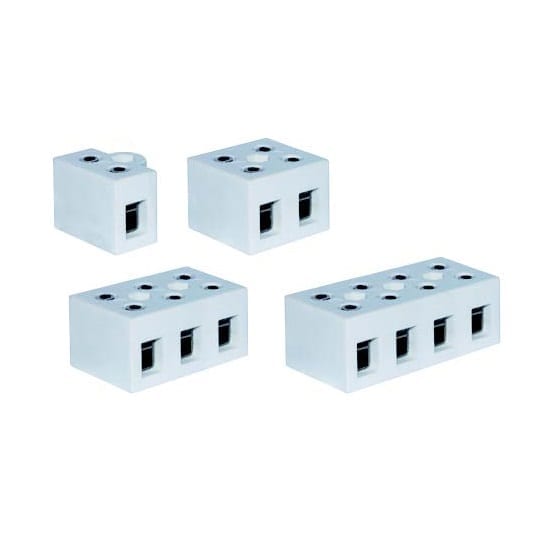
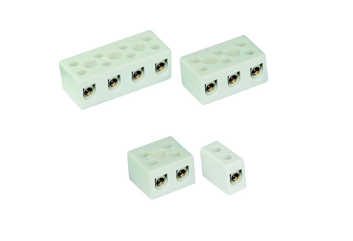
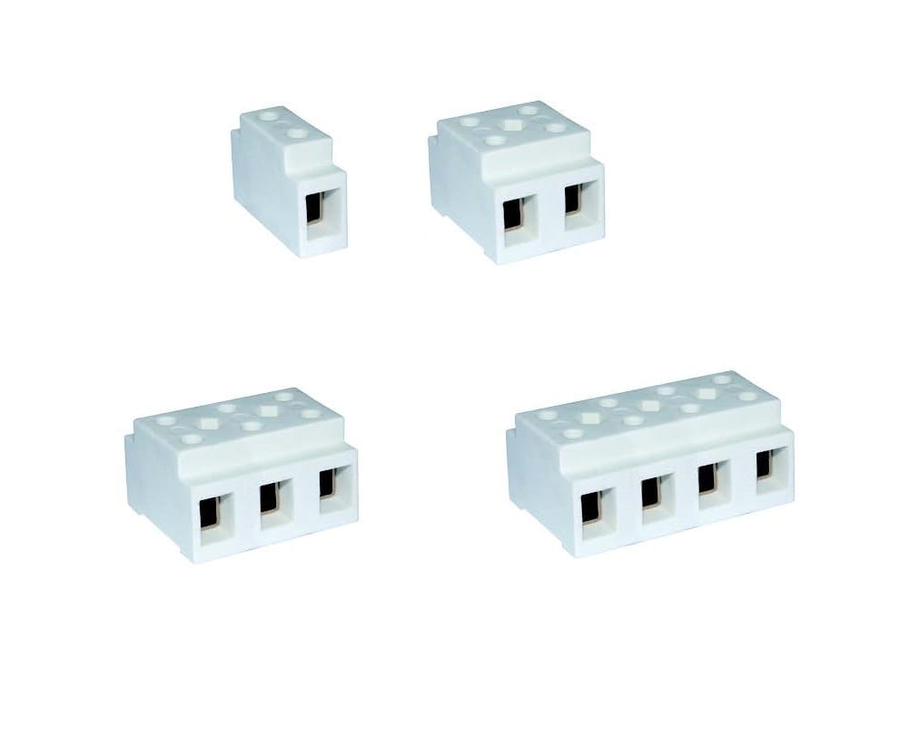
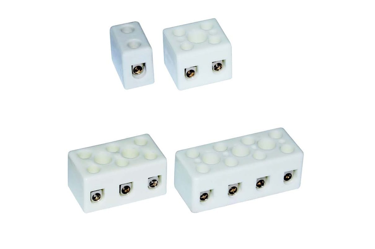
Very high temperature steatite connection blocks. Indirect pressure clamping, with pressure plate, not protected against electric shocks, 750V range
These terminal blocks have been developed to meet the specific needs of connections that must withstand very high temperatures, up to 500°C (930°F) permanently and 700°C (1290°F) peak. They also ensure the continuity of the connection in case of fire up to 950°C (1740°F) (Their subsequent replacement is then necessary). They are particularly intended for road tunnels, public transport tunnels (trains, subways), boat and submarine parts that must withstand a fire.
| Voltage | |
|---|---|
| Ways | |
| Conductor cross-sections (mm²) | |
| Max operating temperature (°C) | |
| Max peak temperature (°C) |
Applications: These terminal blocks have been developed to meet the specific needs of connections that must withstand very high temperatures, up to 500°C (930°F) permanently and 700°C (1290°F) peak. They also ensure the continuity of the connection in case of fire up to 950°C (1740°F) (Their subsequent replacement is then necessary). They are particularly intended for road tunnels, public transport tunnels (trains, subways), boat and submarine parts that must withstand a fire, but also for furnace connections when the ambient temperature is very high at all times. Because of their construction, they are non-flammable and resistant to moisture. Although standards IEC (EN) 60998-1 and IEC (EN) 60998-2 have not provided for the special temperature holding conditions of these terminal blocks, their construction meets their specifications (where applicable), for a maximum voltage of 750V.
At 700°C, in 230V, the leakage current to earth is about 0.1milliamperes. The IEC 60331-21 and IEC 60331-11 standards for fire resistance of cables require a maximum leakage current of 2A at 850°C. It is reached only around 900°C in these terminals, for a voltage of 230V.
Ceramic: Steatite type C221, unglazed, slightly creamy color.
Typical isolation resistors between two terminals (500V measuring voltage):
- at 20°C (70°F): > 100 GΩ
- at 100°C (212°F): > 100 GΩ
- at 200°C (390°F): 90 GΩ
- at 300°C (570°F): 55 GΩ
- at 400°C (750°F): 5 GΩ
- at 500°C (750°F): 90 MΩ
- at 600°C (750°F): 10 MΩ
- at 700°C (750°F): 2,5 MΩ
The EN 60998 standard imposes an insulation resistance greater than 5MΩ. It is reached around 680°C (1250°F) on this model.
Dielectric strength: greater than 9KV at 20°C
Screws: 304 stainless steel, hollow hexagonal head, according to ISO 4762
Terminals: Nickel
Pressure Plates: Nickel
Maximum operating voltage: 750V, in pollution class 3. (Pollution class 3 defines micro environmental conditions causing conductive pollution, or when a non-conductive pollution that may become conductive if condensation occurs).
Insulation distances: Greater than 6mm between mounting face and terminals, between terminals, and between two connection blocks mounted side by side.
Live parts: Not protected against accidental electrical contact.
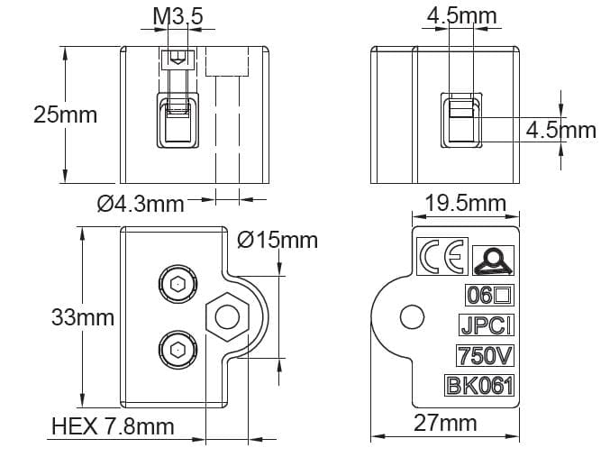
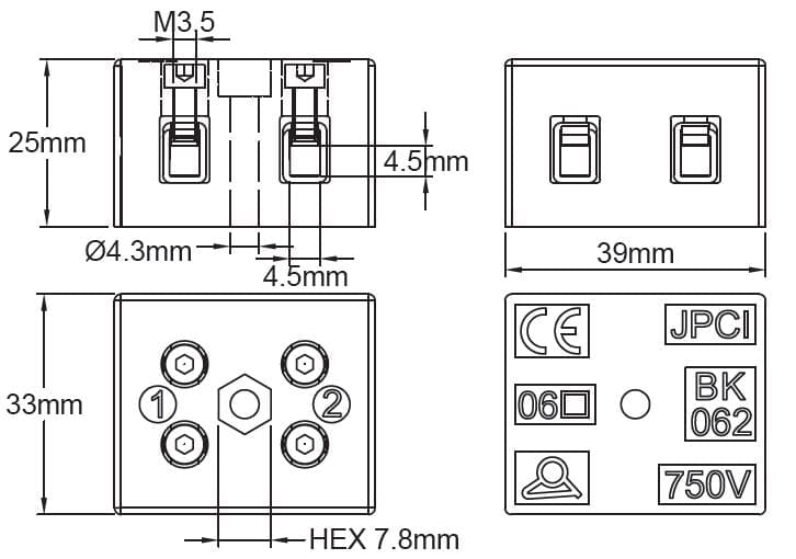
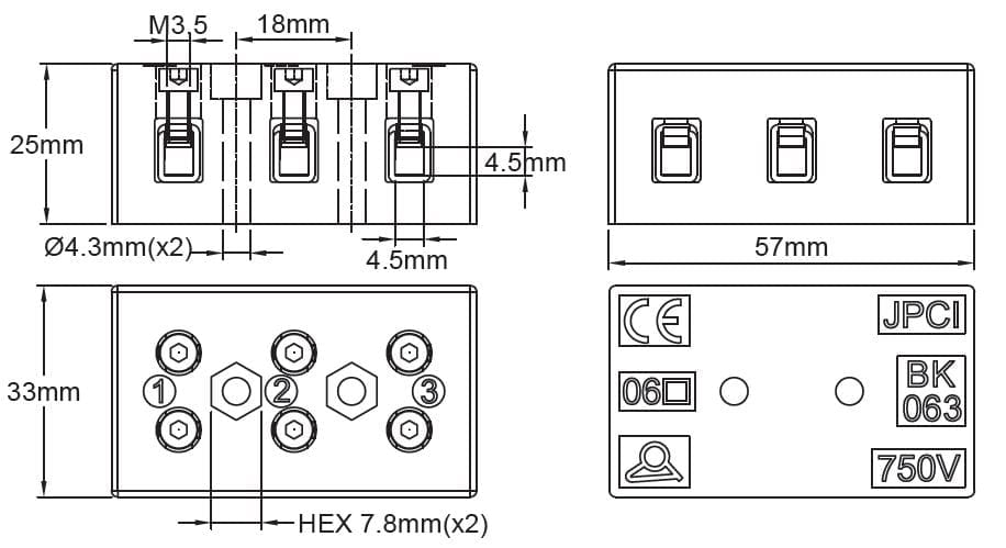
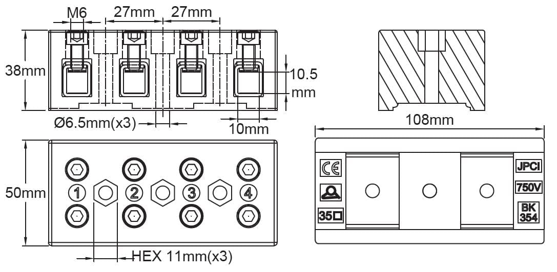
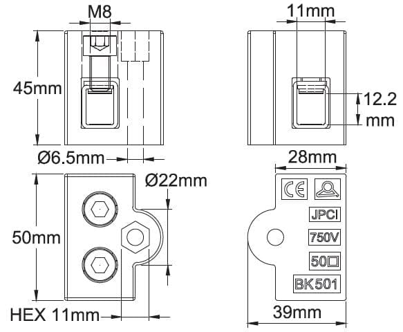
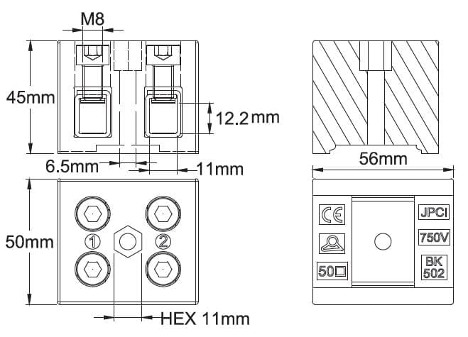
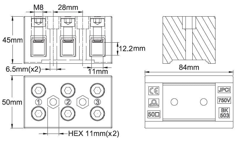
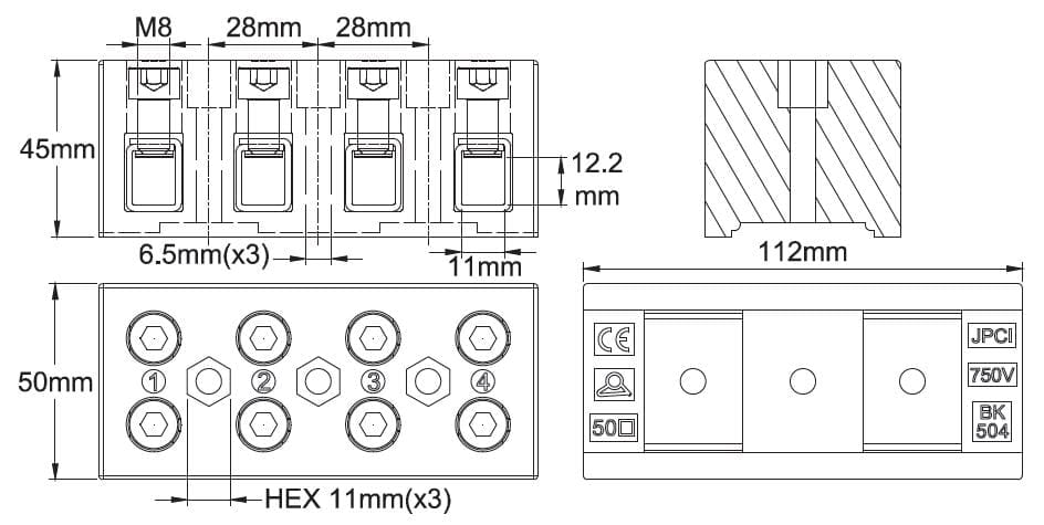
Mounting: With the exception of the single-wire terminals, the terminal blocks have one or two holes for installing a fixing screw on a wall. A hexagonal housing makes it possible to place a round-headed or hexagonal screw, or a nut. This allows mounting with clamping by the front or the back. The largest dimensions (35 and 50mm²) can accommodate a 35mm Din rail mounting clip.
Important note: These terminal blocks must imperatively be fixed in order to prevent their movement for any reason in the box in which they are mounted, and consequently put them in a position where the insulation distances are no longer respected.
Maximum ambient temperature:
- Permanent: 500°C / 930°F
- Peak (<90 minutes): 700°C / 1290°F
The temperature resistance values of the nickel terminals were validated by wire pull tests according to EN 60998, performed after 48H at 500°C (930°F) and 90 minutes at 700°C (1290°F).
Partially applicable standards: (IEC) EN 60998-1; (IEC) EN 60998-2-1.
Caution: Special care must be taken to avoid electric shock. These terminal blocks are not usable in places accessible without tools. They must be mounted in protective boxes. Respect the distances in the air of at least 6mm between the live parts and the walls of the protective case. Other rules may apply according to local safety regulations.
Section possible des conducteurs:
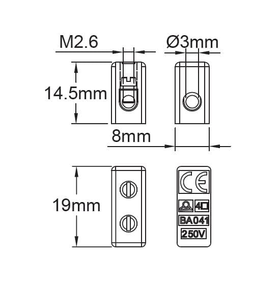
| 6 mm² | |
| BK061, BK062, BK063, BK064 | |
| Solid conductor | 6mm²/4mm²/2.5mm²/AWG10/AWG12/AWG14 |
| stranded conductor | 4mm²/2.5mm²/AWG12/AWG14 |
| Current carrying capacity | 41A per terminal |
| Screw thread | M3 |
| Tightening torque | 0.5 N.m |
| 10 mm² | |
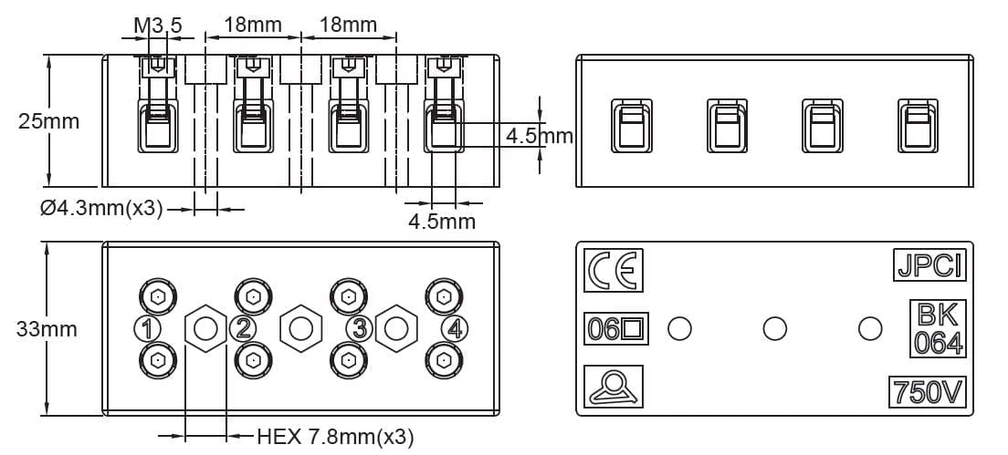
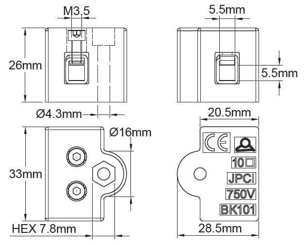
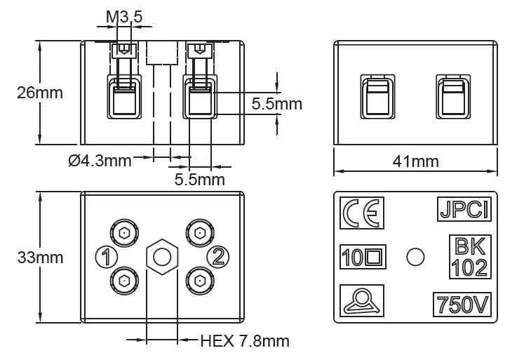
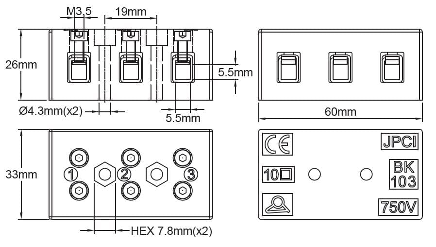
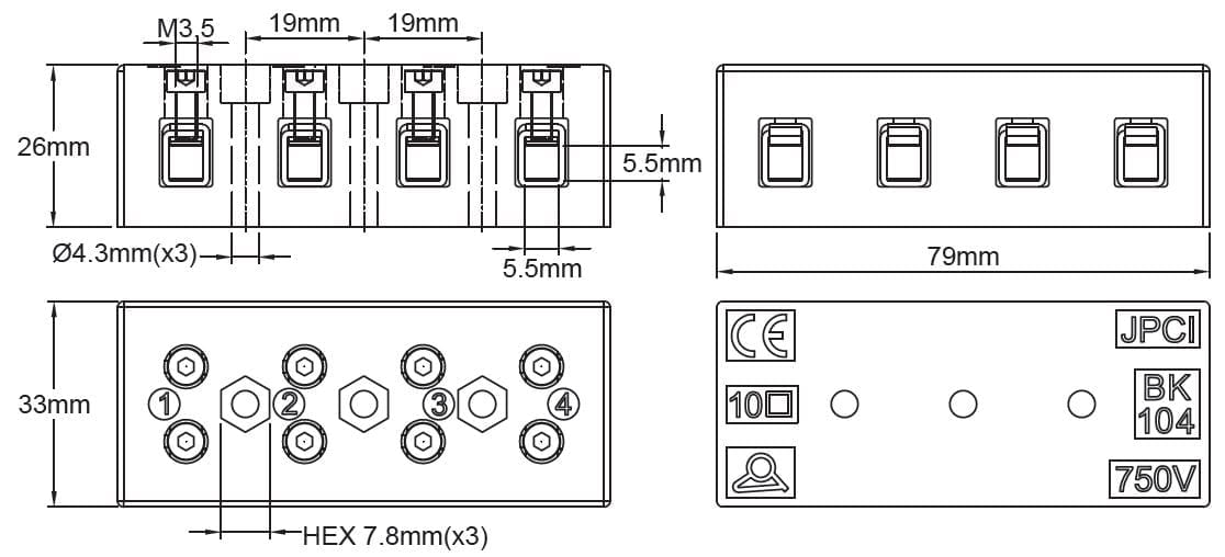
| BK101, BK102, BK103, BK104 | |
| Solid conductor | 10mm²/6mm²/4mm²/AWG8/AWG10/AWG12 |
| stranded conductor | 6mm²/4mm²/AWG10/AWG12 |
| Current carrying capacity | 57A per terminal |
| Screw thread | M3.5 |
| Tightening torque | 0.8 N.m |
| 16 mm² | |
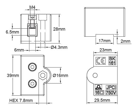
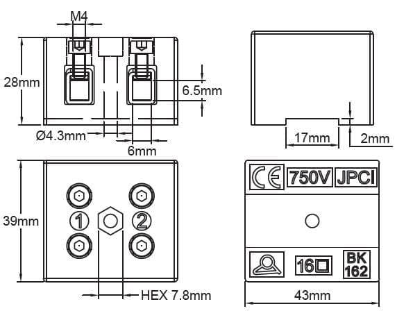
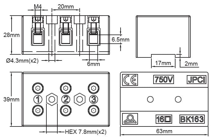
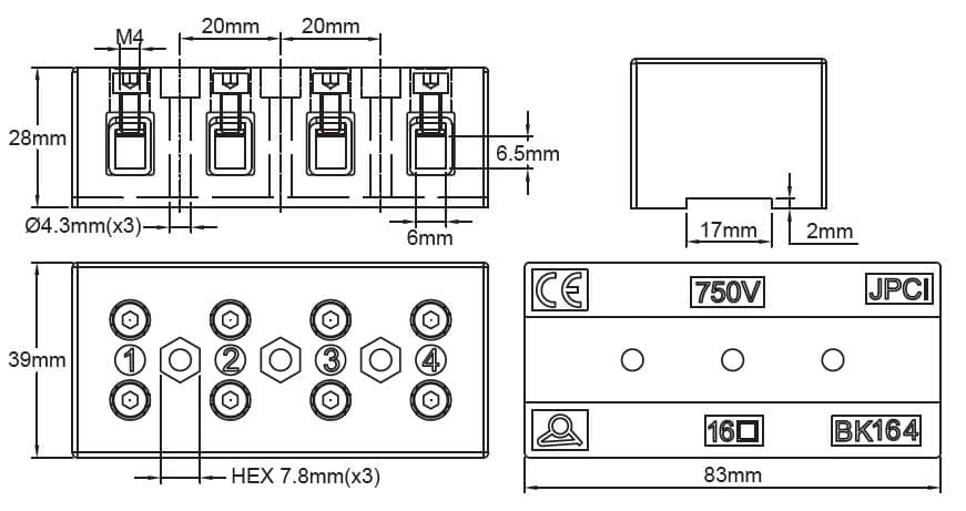
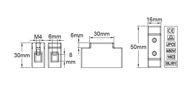
| BK161, BK162, BK163, BK164
Mounting on 16x3mm rail is possible |
|
| Solid conductor | 16mm²/10mm²/6mm²/AWG6/AWG8/AWG10 |
| stranded conductor | 10mm²/6mm²/AWG8/AWG10 |
| Current carrying capacity | 79A per terminal |
| Screw thread | M4 |
| Tightening torque | 1.2 N.m |
| 25 mm² | |
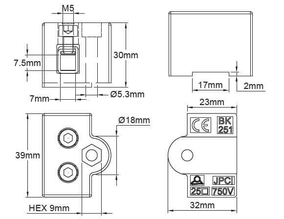
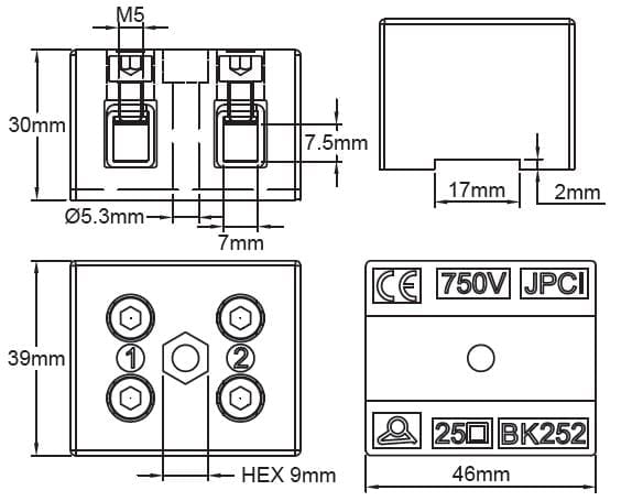
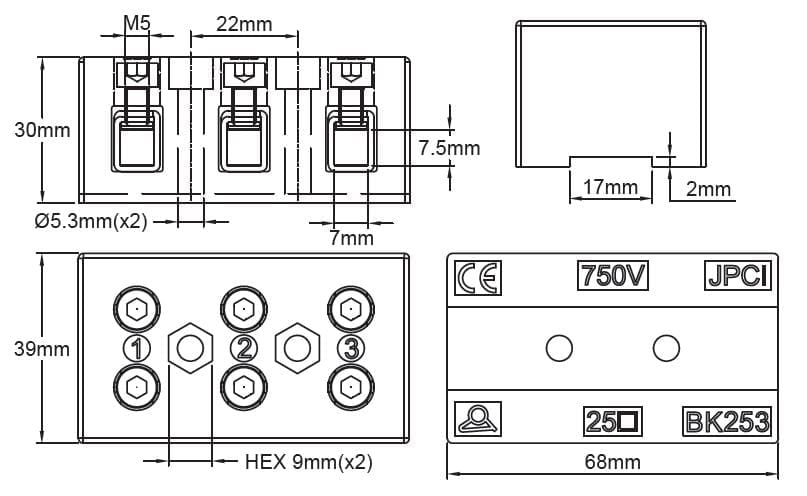
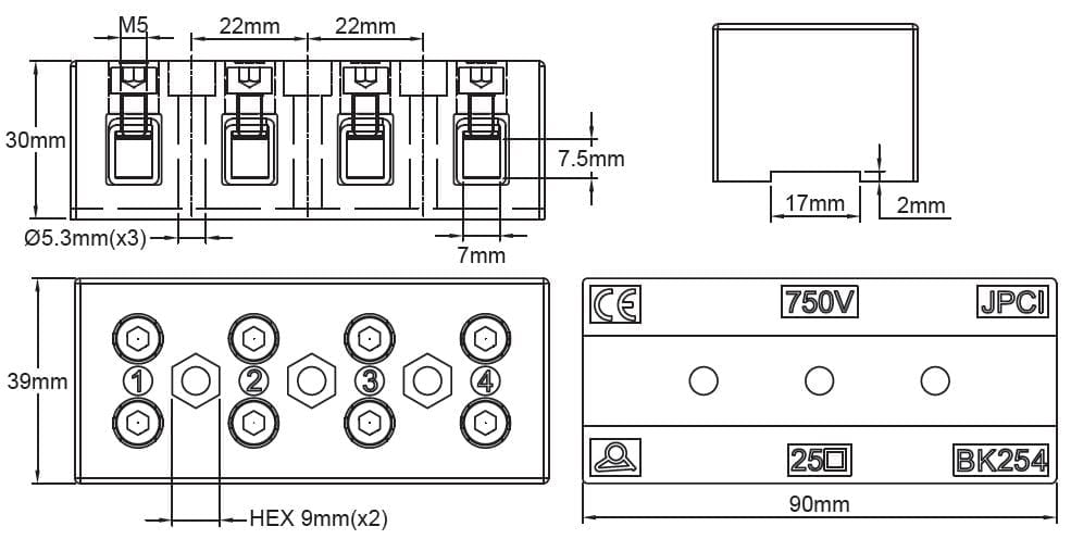
| BK251, BK252, BK253, BK254
Mounting on 16x3mm rail is possible |
|
| Solid conductor | 25mm²/16mm²/10mm²/AWG4/AWG6/AWG8 |
| stranded conductor | 16mm²/10mm²/AWG6/AWG8 |
| Current carrying capacity | 101A per terminal |
| Screw thread | M5 |
| Tightening torque | 2 N.m |
| 35 mm² | |
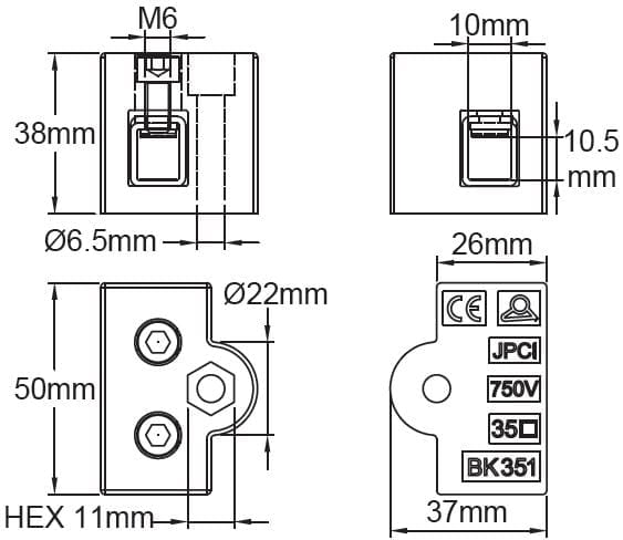
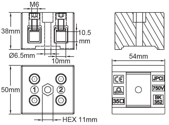
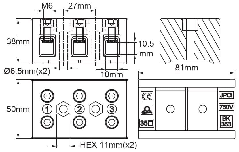
| BK351, BK352, BK353, BK354
Mounting on 35mm Din rail is possible |
|
| Solid conductor | 35mm²/25mm²/16mm²/AWG2/AWG4/AWG6 |
| stranded conductor | 25mm²/16mm²/AWG4/AWG6 |
| Current carrying capacity | 125A per terminal |
| Screw thread | M6 |
| Tightening torque | 2.5 N.m |
| 50 mm²** | |
| BK501, BK502, BK503, BK504
Mounting on 35mm Din rail is possible |
|
| Solid conductor | 50mm²/35mm²/25mm²/AWG0/AWG2/AWG4 |
| stranded conductor | 35mm²/25mm²/AWG2/AWG4 |
| Current carrying capacity | 150A** per terminal |
| Screw thread | M8 |
| Tightening torque | 3.5 N.m |
** : These cross-section and rating do not exist in EN60998 which is limited to 35mm², so these values are taken from EN60947.
Downloads
Datasheets
Drawings
Related products
Room and antifreeze temperature control boxes
T connection box for heat tracing cables with antifreeze thermostat
Connection blocks
Connection blocks
Accessories for immersion heaters
Technical informations associated to this product
-
Historical introduction of ceramics used in connection blocks
Hard Porcelain, originated from China, whose manufacturing process has been closely guarded for centuries, owes its characteristics of whiteness, fineness, resistance to temperature, and hardness to the use of two particular minerals, kaolin, ("Gao Ling Tu 高 岭 土 " in Chinese, which can be translated as "Clay of Gao Ling City", located north-east of Jingdezhen in Jiang Xi Province), and "Pu Tong Ci 普 通 瓷 " (translation: common ceramic). -
Technical introduction of connection blocks made in ceramic and polyamide
Ceramic was the first insulating material used in the electrical connection terminals. Mechanically resistant, exceptionally fire resistant, excellent electrical insulator, it had all the qualifications. Produced from locally available raw materials, ceramic and porcelain glazed electro-technical parts were essential in the beginnings of electricity until the appearance of Bakelite in the 1930s, then of engineered thermoplastics to 1960. -
Main properties of brass
According to the Directive 2011/65/ dated June 8, 2011 (Rohs), copper alloys are allowed to have a maximum of 4% by weight of lead as an alloying element. (Provisions of Article 4 and paragraph 1 of Annex II, limit value set by 6c of Annex III) -
Main properties of usual stainless steels
According to the Directive 2011/65/ dated June 8, 2011 (Rohs), stainless steel alloys are allowed to have a maximum of 0.1% by weight of lead, lead, mercury, hexavalent chromium, PBB (Polybrominated biphenyls), PBDE (Polybrominated Diphenyl Ethers) and 0.01% of Cadmium in weight.

