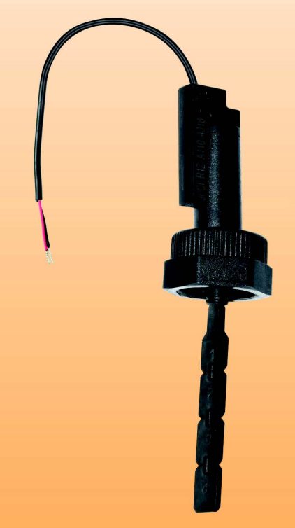
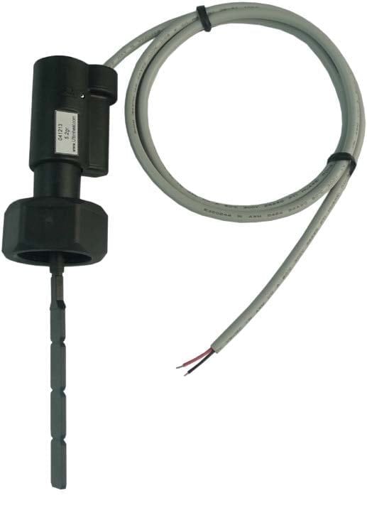
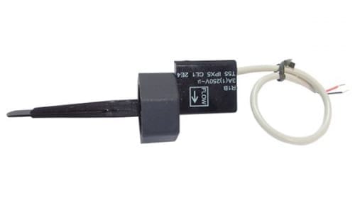
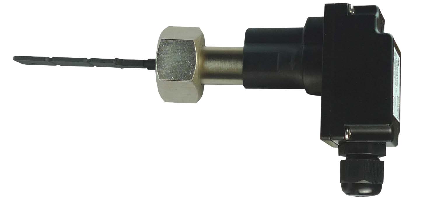
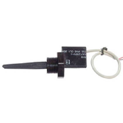
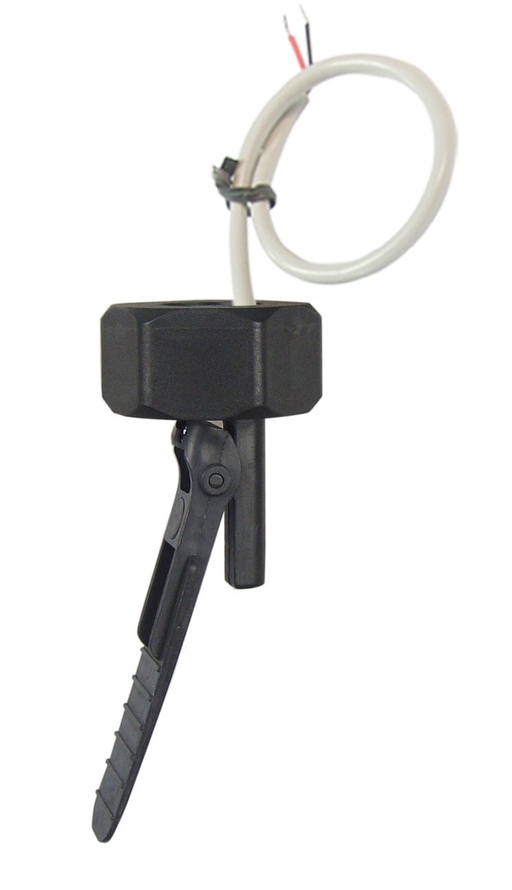
paddle flow switch with low volatge reed switch contact, simplified model R1Z
Large quantities applications in flow detection in low voltage electronic circuits. The most economical model. Recommended mounting position is on horizontal pipes. Can be mounted in any position with a small drift in the calibration because of the paddle weight. Can be used on 15 to 100mm diameter water pipes.
Main uses: Large quantities applications in flow detection in low voltage electronic circuits. The most economical model. Recommended mounting position is on horizontal pipes. Can be mounted in any position with a small drift in the calibration because of the paddle weight. Can be used on 15 to 100mm diameter water pipes.
Functional principle:
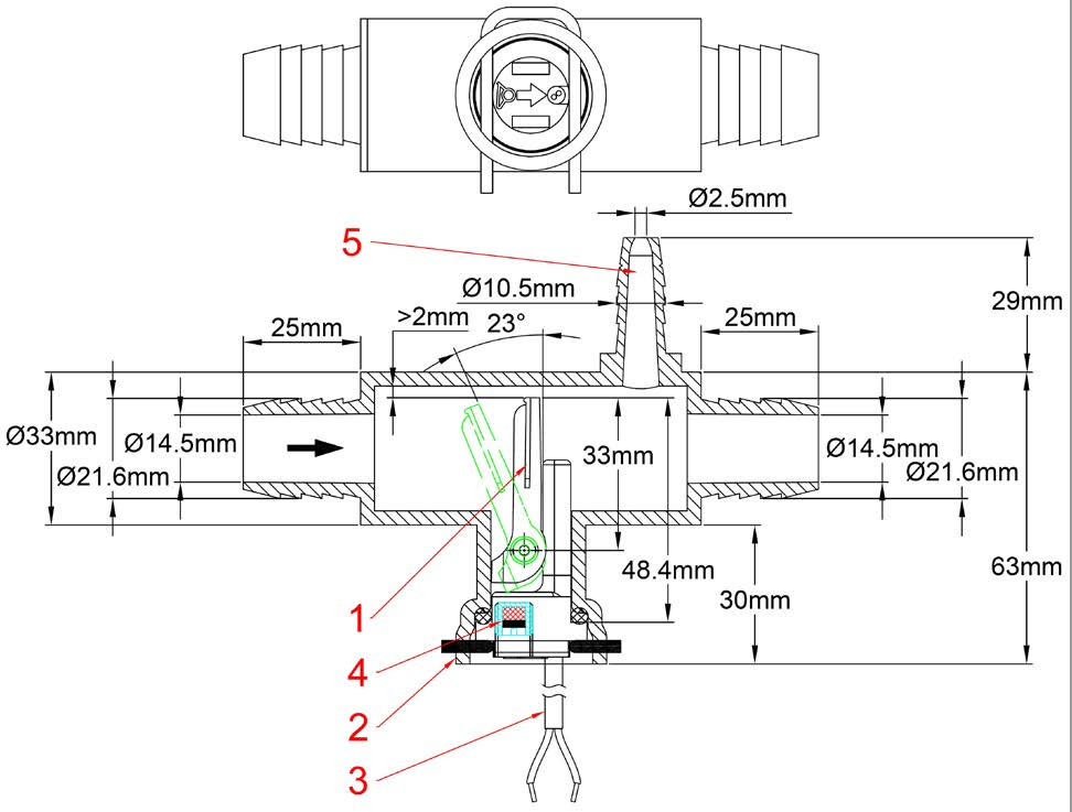
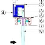
Balanced magnetic pallet mounted perpendicular to the flow and activating a reed switch through the wall. The return of the paddle is made by magnetic action, without spring. No seal or liquid can pass between the piping system and the electrical contact. Suitable for corrosive water pools and spas and salination chlorination and bromination systems. Must not be used for water containing magnetic particles or high viscosity liquids, which block the movement of the paddle.
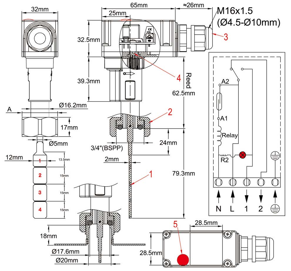
Adjustment: By cleaving the paddle. These flow switches are available with 6 factory setting calibrations, corresponding to operating forces of 0.08N (8gr), 0.09N (9gr), 0.11N (11gr), 0.14N (14gr), 0.18N (18g), 0.29N (29gr). Values are measured at the end of paddle N°1.
Paddle shaft: Titanium (Patented), provides an outstanding corrosion resistance (contrary to stainless steel), does not break (contrary to ceramic shafts models), and improved mechanical live. Suitable for corrosive water pools and spas and salination chlorination and bromination systems.
Main housing material: PPO, fiber glass reinforced for improved pressure resistance, usable with potable water.
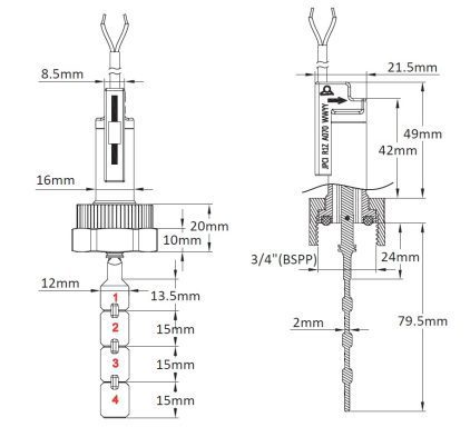
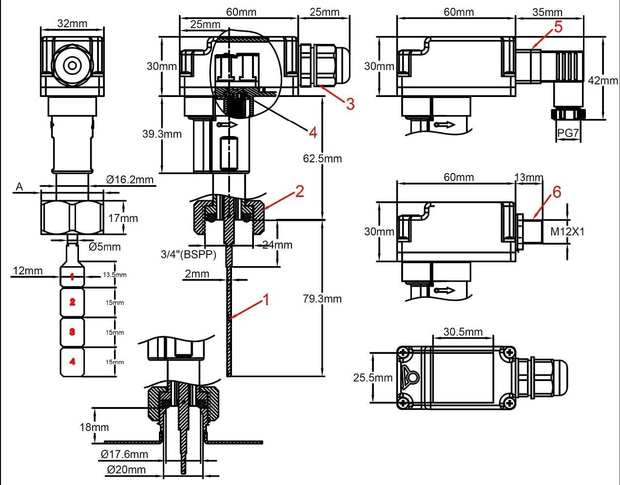
Paddle: PPO, 12 mm width, can be cleaved into 4 sections numbered 1 to 4 for pipe diameter adjustment.
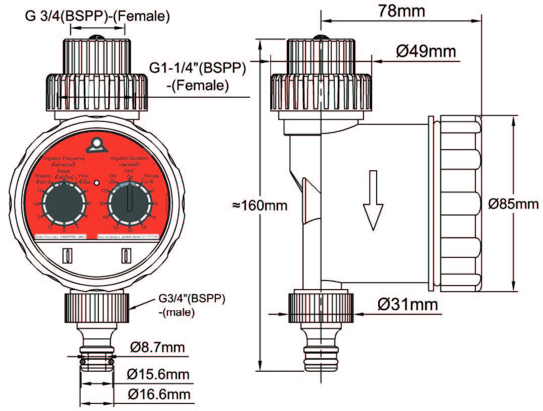
Pipe mounting: Fiber glass reinforced union nut, ¾” BSPP, mounting on ¾” BSPP male fitting with gasket. Recommended torque: 7±1Nm.
Gasket: NBR. (A special silicone gasket, available on request, has been developed for water with metallic particles to limit their access to magnetic parts).
Electrical rating: Max 0.SA, Max 10VA, Max 80V, resistive load. Use on inductive circuits reduces electrical rating. We recommend to protect the reed switch with contact protection device when used in inductive loads.
Electric contact type: Normally open, closes by flow rise.
Liquid compatibility: For use with clean water and liquids without magnetic particles and without chemical incompatibility with PPO and titanium.
Nominal pressure at 20°C: 0.6MPa (PN6).
Liquid temperature range: 5 to 95°C.
Ambient temperature range: 5 to 80°C.
Ingress protection: lP65.
Calibration tolerances: +/-15%
Electrical connection: 2 x AWG26 (0.1Smm2) cable, PVC insulation, T80°C.
Installation instructions:
- Check carefully the paddle orientation: The arrow on housing must be exactly parallel to the
- A 4 to S mm minimum gap must be respected between end of the paddle and tube wall opposite to the
- We recommend the use of nozzles of length less than or equal to 18mm between the gasket seat and the inside of the tube and with an inner diameter greater than or equal to 13.S mm, to avoid blocking of the paddle
Accessories: ¾” male PVC saddles for DN40 to DN100 (Outside dimeter} PVC pipes, and other fittings: see section 8 of this catalogue.
Options (MOQ apply): cable with connector or terminals, other cable length,
Important notice: ln the case of plastic pipes (PVC, PE}, the DN (nominal diameter) corresponds to the outside diameter and wall thickness is variable depending on the application. This must be taken into account to avoid blocking the paddle. ln the case of metal pipes, the inner diameter corresponds to the DN. Flow value data are for tubes whose internal diameter corresponds to DN.
Average flow detection values (Liters/min)
| Operating force (g) |
Paddle number |
Pipe ID (mm) | |||||||||
| 15 | 20 | 25 | 32 | 40 | |||||||
| *Close | **Open | *Close | **Open | *Close | **Open | *Close | **Open | *Close | **Open | ||
| 8 | 1 | 5.1 | 4 | 8.3 | 7.3 | 17 L/min | 15 | 32 | 29 | ||
| 9 | 1 | 5.8 | 4.1 | 10 | 8.3 | 18 | 17 | 36 | 35 | ||
| 11 | 1 | 6.3 | 4.4 | 11.5 | 9.5 | 20 | 18 | 42 | 36 | ||
| 14 | 1 | 7.3 | 4.8 | 12.5 | 10 | 22 | 21 | 46 | 40 | ||
| 18 | 1 | 8.1 | 5.4 | 14 | 11 | 24 | 23 | 50 | 44 | ||
| 29 | 1 | 8.8 | 5.6 | 15.5 | 12 | 27 | 26 | 57 | 48 | ||
| 8 | 1+2 | 30 | 26 | ||||||||
| 9 | 1+2 | 32 | 29 | ||||||||
| 11 | 1+2 | 36 | 32 | ||||||||
| 14 | 1+2 | 38 | 34 | ||||||||
| 18 | 1+2 | 46 | 35 | ||||||||
| 29 | 1+2 | 50 | 43 | ||||||||
| * Close by flow rise (L/min) of contact open at no flow position. ** Open by flow decrease (L/min) of contact open at no flow position. Average values for indication only. Standard tolerances ±15% | |||||||||||
| Operating force (g) |
Paddle number |
Pipe ID (mm) | |||||||
| 50 | 63 | 80 | 100 | ||||||
| *Close | **Open | *Close | **Open | *Close | **Open | *Close | **Open | ||
| 8 | 1+2+3 | 42.2 | 33.4 | S6.9 | 37.4 | ||||
| 9 | 1+2+3 | 48.6 | 37 | 66.85 | 40.44 | ||||
| 11 | 1+2+3 | 53.75 | 44.S | 73.8 | 46.8 | ||||
| 14 | 1+2+3 | 57.7 | 44.S | 79.3 | 48.4 | ||||
| 18 | 1+2+3 | 61.4 | S0.4 | 85.5 | 57.9 | ||||
| 29 | 1+2+3 | 66.8 | 58.4 | 95.1 | 66.1 | ||||
| 8 | 1+2+3+4 | 98.2 | 40.8 | 156.7 | S3.S | ||||
| 9 | 1+2+3+4 | 111.85 | 46.2 | 181.S5 | S1.9 | ||||
| 11 | 1+2+3+4 | 118.8 | 46.4 | 191.4 | 58.5 | ||||
| 14 | 1+2+3+4 | 144.45 | S9.1 | 211.2 | 60.4 | ||||
| 18 | 1+2+3+4 | 150.6 | 60.2 | 223.95 | 64.9 | ||||
| 29 | 1+2+3+4 | 162.3 | 66.4 | 235.1 | 74.2 | ||||
| * Close by flow rise (L/min) of contact open at no flow position.
** Open by flow decrease (L/min) of contact open at no flow position. Average values for indication only. Standard tolerances ±15% |
|||||||||
Main references
| Calibration (Calibration force ±15%,
measured at end of paddle N°1) |
500mm cable | 2m cable | 3m cable |
| 8 gr | R1Z286680G3SN0S0 | R1Z286680G3SN200 | R1Z286680G3SN300 |
| 9 gr | R1Z296680G3SN0S0 | R1Z296680G3SN200 | R1Z296680G3SN300 |
| 11 gr | R1Z2B6680G3SN0S0 | R1Z2B6680G3SN200 | R1Z2B6680G3SN300 |
| 14 gr | R1Z2E6680G3SN0S0 | R1Z2E6680G3SN200 | R1Z2E6680G3SN300 |
| 19 gr | R1Z2J6680G3SN0S0 | R1Z2J6680G3SN200 | R1Z2J6680G3SN300 |
| 29 gr | R1Z2S6680G3SN0S0 | R1Z2S6680G3SN200 | R1Z2S6680G3SN300 |
OEM paddles can be made on order (MOQ apply}.
Downloads
Documents
Related products
Paddle flow switches
Paddle flow switches
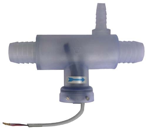
Paddle flow switches, reed switch contact, inside barbed tee for 1”soft tube
Paddle flow switches
Paddle flow switches, reed switch contact, built-in 16A SPDT relay
Paddle flow switches
Paddle flow switches, micro-switch contact, 3/4” BSPP union nut
Paddle flow switches
Paddle flow switches, reed switch contact, external brass body
Paddle flow switches
Paddle flow switches, reed switch contact, 3/4”union nut, slim design
FLOW SWITCHES
Technical informations associated to this product
-
Flow switches historical foreword
In antiquity, the flow measurement was one of the first means of time measurement. But it was not until the steam engines development and the need to control their water supply, that measuring devices were developed. -
Flow switches technical foreword
A certain force is required to actuate the electrical contact device. It can range from a few tenths of grams for systems with reed contacts with a power rating of 10 to 20VA (0.5Amp), to 50 grams for snap action micro-switches with a 5Amp 250V rating -
Reed switches contacts protection
1. The electrical contact system: reed switch or micro-switch A certain force is required to actuate the electrical contact device. It can range from a few tenths of grams for systems with reed contacts with a power rating of 10 to 20VA (0.5Amp), to 50 grams for snap action micro-switches with a 5Amp 250V rating [...]


