Product query
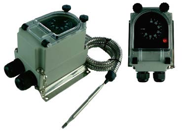
Bulb and capillary thermostat IP66, IK10
Applications
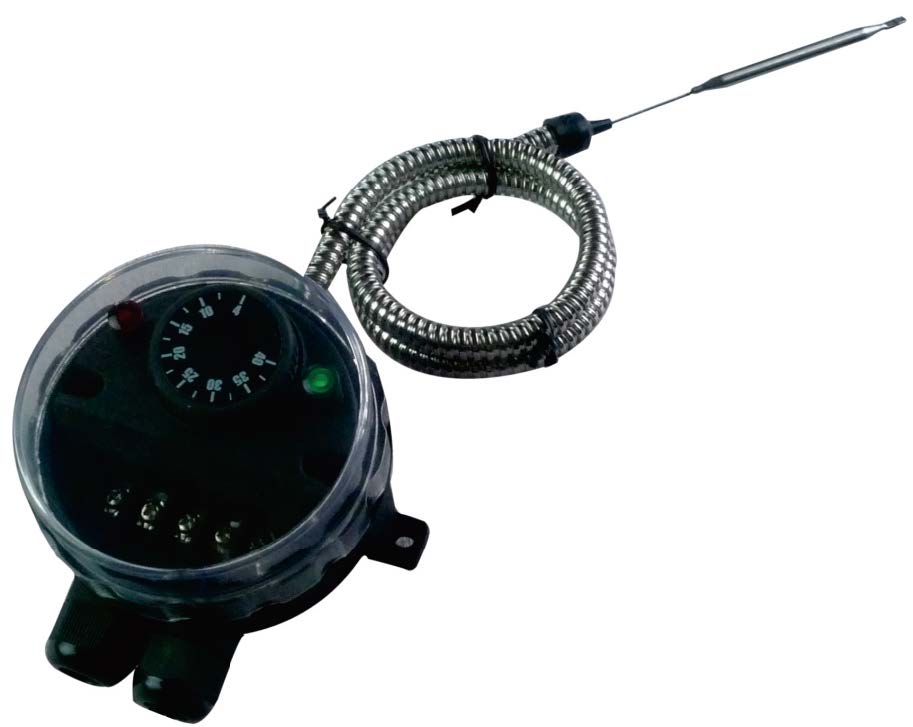
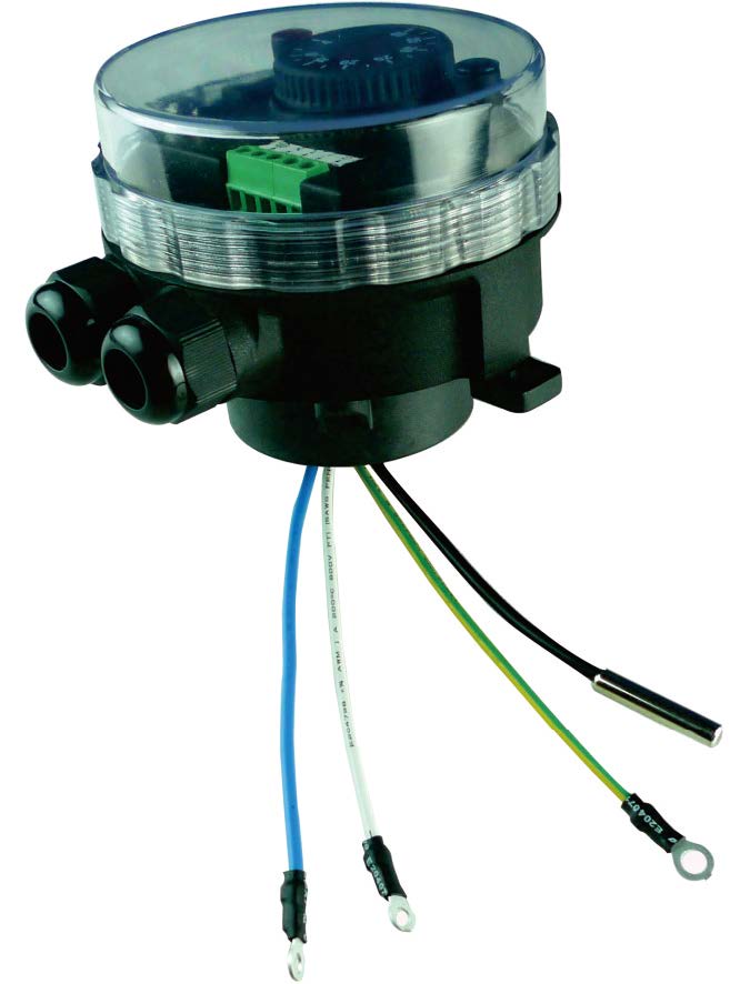
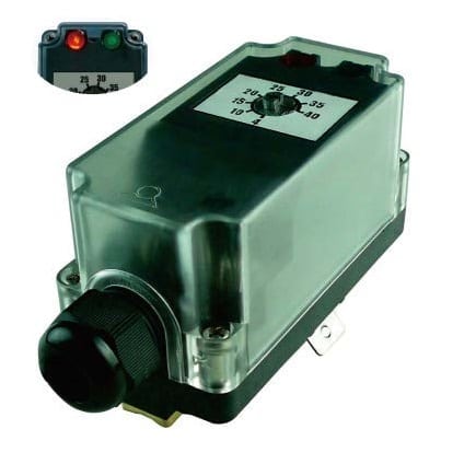
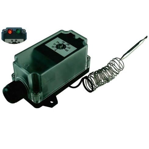
-Equipment requesting a very strong resistance to water ingress. The transparent cover allows to visualize the set point and the 2 pilot lights
-Remote control in usual industrial application and environment, not hazardous areas.
| Housing raw material | |
|---|---|
| Color | |
| Ingress protection | |
| Mechanical protection | |
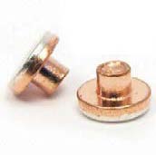
| Contact Material | |
| Electrical rating | |
| Voltage | |
| Electrical life (cycles at rated value) | |
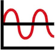
| Measurement type | |
| Sensing element | |
| Differential (°C) | |
| Setting adjustment |
| Enclosure | Type | Operation | Contact | Measurement | Ranges °C | Models |
| IP66, IK10 | Control | Mechanical | SPDT | Remote | 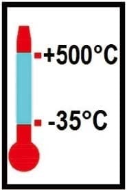 |
YF9GNC |
|
Material |
 |
 |
 |
 |
||
|
PA66 & PC |
Applications
-Equipment requesting a very strong resistance to water ingress. The transparent cover allows to visualize the set point and the 2 pilot lights
-Remote control in usual industrial application and environment, not hazardous areas.
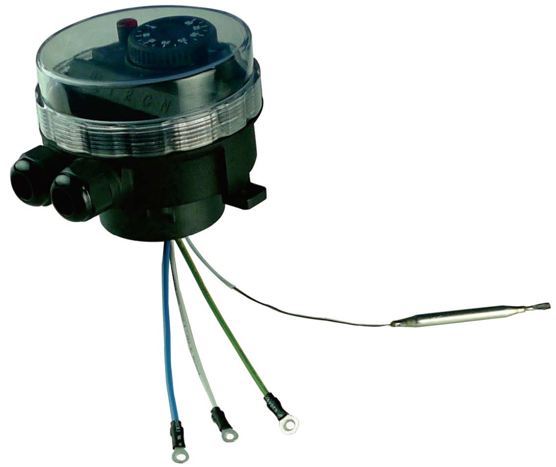
Housing:Protection class IP 66 upon EN 60529 (waterproof spray water under high pressure and sea splashes, totally dust tight). Body in black PA66, fiber glass reinforced. The transparent polycarbonate cover can be unscrewed by hand, but it is also possible to use a hook spanner. Mechanical impact resistance : IK10. High UV resistance.
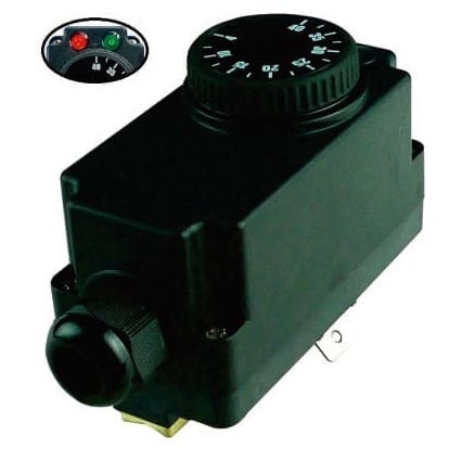
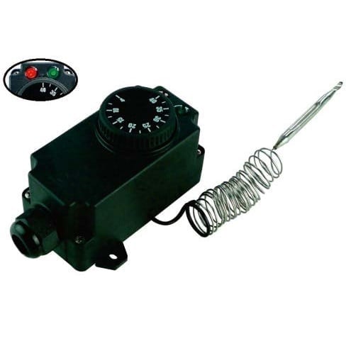
Set point adjustment:By °C printed knob. All types have an adjustable rotation limit system located inside the knob that allows reducing the set point adjustment span. °F printed knobs available as an option.
Action:Temperature control. On-Off action.
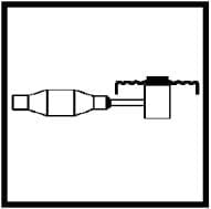
Sensing element:Liquid expansion bulb and capillary. The capillary is protected by a stainless steel corrugated pipe terminated by a silicone tip. A plastic cap plug provided as standard accessory allows locking the flexible metal conduit inside a pocket (See pockets in the accessories section).
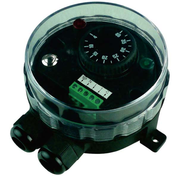
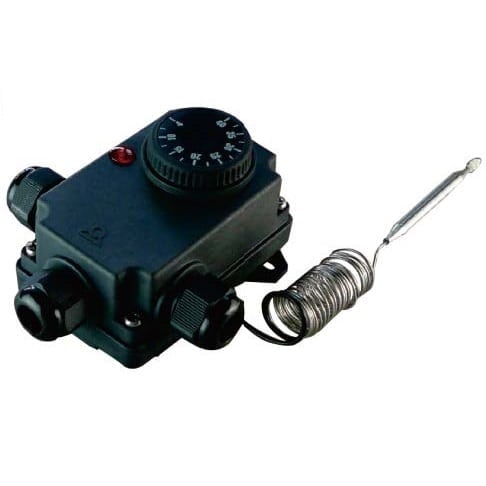
Pilot lights:One pilot light visualizes the thermostat contact output position. The other visualizes the power supply input. Phase and neutral electrical line supply are mandatory for these pilot lights.
Set point adjustment ranges:-35+35°C (-30+95°F); -10+40°C (15-105°F); 4-40°C (40-105°F); 0-60°C (32-140°F); 0-90°C (32-195°F); 30-90°C (85-195°F); 30-110°C (85-230°F); 50-200°C (120-390°F); 50-300°C (120-570°F); 100-400°C (210-750°F); 100-500° C(210-930°F)
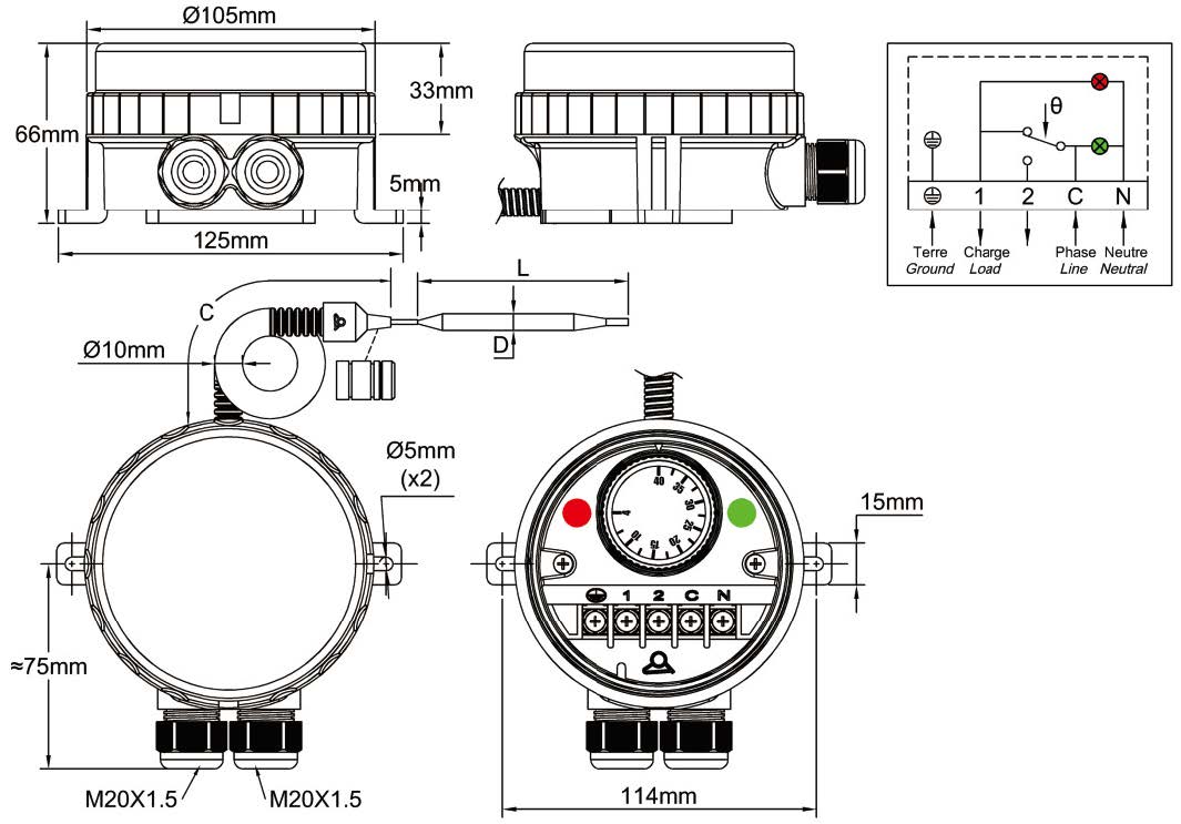
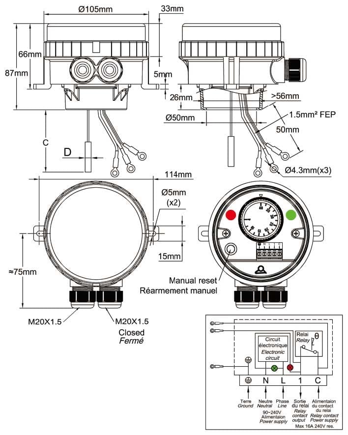
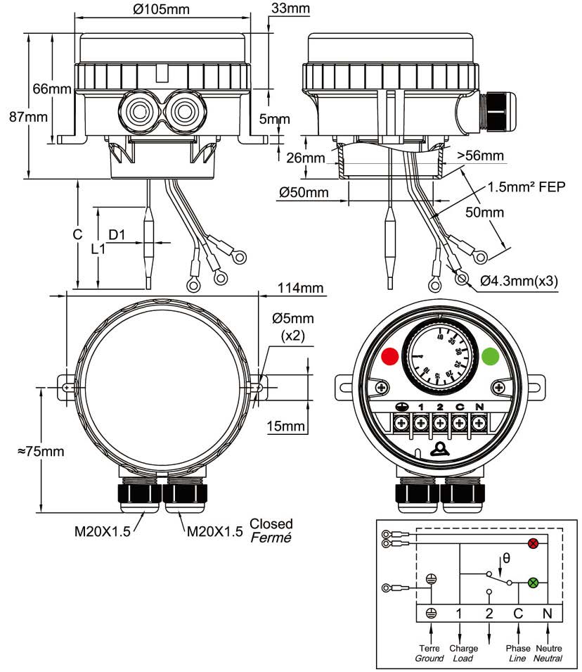
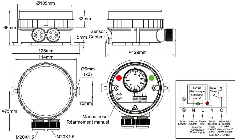
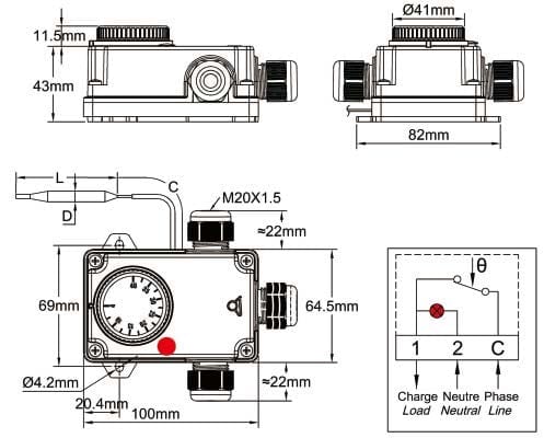
Cable input and output:Two M20 cable glands, built-in black PA66.
Electrical connections:Inside, on screw terminal connection block. It is possible to connect 2 wires 1.5mm² on each terminal.
Earthing:Internal screw terminal.
Mounting:Wall mounting, by 2 legs with holes for screws dia. 4 to 5 mm, 114 mm distance
Identification:Identification label on backside
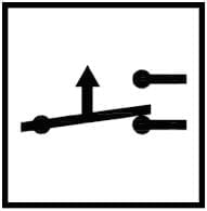
Contact:SPDT
Electrical rating, resistive loads:
-Open on temperature rise contact (C-1) 16A 250V, 50 ~60Hz: >100000 cycles,
20A 250V, 50 ~60Hz: ≥ 50000 cycles,
10A 400V, 50 ~60Hz: ≥ 50000 cycles.
-Close on temperature rise contact (C-2): 6A 250V 50 ~60Hz: >100000 cycles
Electrical rating, inductive loads:
-Open on temperature rise contact (C-1): 2.6A 250V, 50 ~60Hz: >100000 cycles
-Close on temperature rise contact (C-2):0.6A 250V 50 ~60Hz: >100000 cycles.
Minimum storage temperature:-35°C (-30°F)
Maximum ambient temperature:60°C (140°F)
For more technical information ask 8G thermostat technical data sheet.
Main references
| Temperature range
°C (°F) |
References | Capillary length (C, mm) | Bulb diameter (D, mm) | Bulb length (E, mm) | Differential°C (°F) | Max temperature on bulb °C (°F) |
| -35+35°C (-30+95°F) | YF9GNC35035156ZJ | 1500 | 6 | 120±5 | 1,6±1°C (2,9±2°F) | 60°C (140°F) |
| -10+40°C (15-105°F) | YF9GNC10040156ZJ | 1500 | 6 | 107±5 | 1,5±1°C (2,7±2°F) | 70°C (158°F) |
| 4-40°C (40-105°F) | YF9GNC04040156ZJ | 1500 | 6 | 120±5 | 1±0.5°C (1,8±1°F) | 70°C (158°F) |
| 0-60°C (32-140°F) | YF9GNC00060156ZJ | 1500 | 6 | 86±5 | 2.5±1°C (4,5±1,8°F) | 80°C (176°F) |
| 0-90°C (32-195°F) | YF9GNC00090156ZJ | 1500 | 6 | 98±5 | 2.5±1°C (4,5±1,8°F) | 120°C (250°F) |
| 30-90°C (85-195°F) | YF9GNC30090156ZJ | 1500 | 6 | 98±5 | 2.5±1°C (4,5±1,8°F) | 120°C (250°F) |
| 30-110°C (85-230°F) | YF9GNC30110156ZJ | 1500 | 6 | 86±5 | 2.5±1°C (4,5±1,8°F) | 140°C (284°F) |
| 50-200°C (120-390°F) | YF9GNC50200156ZJ | 1500 | 6 | 65±5 | 4±2°C (7±3.6°F) | 230°C (446°F) |
| 50-300°C (120-570°F) | YF9GNC50300153ZJ | 1500 | 3 | 145±5 | 10°C±2°C (18±3.6°F) | 330°C (626°F) |
| 100-400°C (210-750°F) | YF9GNCA0400153ZJ | 1500 | 3 | 93±5 | 10°C±2°C (18±3.6°F) | 430°C (800°F) |
| 100-500°C (210-930°F) | YF9GNCA0500144ZJ | 1400 | 4 | 235±5 | 10°C±2°C (18±3.6°F) | 550°C (1000°F) |
Downloadable
Datasheets
Related products
Immersion heater temperature limiter boxes
Immersion heater temperature limiter boxes
Adjustable electronic manual reset limiter for immersion heater IP66, IK10
Immersion heater temperature control boxes
Remote temperature control boxes
Dia. 30 to 70mm pipe mounting thermostat IP55 with 2 built-in pilot lights
Room and antifreeze temperature limiter boxes
Remote temperature control boxes
Bulb and capillary thermostat IP55 with 2 built-in pilot lights
Remote temperature control boxes
Remote temperature control boxes
Technical informations associated to this product
-
Main properties of plastic raw materials used for enclosures
The classic housings, with only 5 sides and a lid, require a long and costly layout, most of the time ignoring the application needs: security, fire resistance, water penetration, shocks, UV, temperature, etc. -
Electrical protection classes
The housings are designed to protect electrical equipment located inside. This protection must be considered in the electrical and environmental angles.) -
Thermostats installation
The proper functioning of a thermostat depends primarily on the correct choice of the component, but also the conditions of its installation. Conditions used to calibrate regulating and control equipment in the factory are always ideal laboratory conditions, ensuring measurement accuracy and repeatability. These conditions are rarely those found in practice when installing thermostats. However, with a minimum of constraints, it is possible to optimize assemblies. -
Electrical contacts
As numerous mechanisms exist, we decided not to distinguish on the basis of constructive technique, but according to their operation speed, which is the key element.

