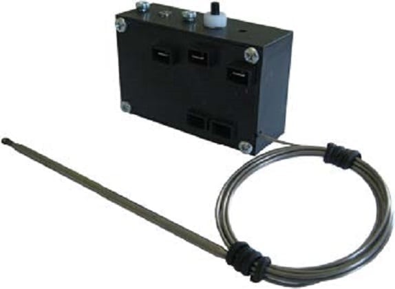
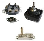
SPNC manual reset high limit, fail safe
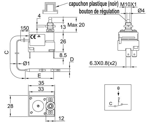
Housing dimensions: 43 x 35 x 29 mm (without terminals)
Bulb and capillary: stainless steel, capillary length 250mm or 1500 mm, 150 mm long PVC sleeve on capillary.
| Electrical rating | |
|---|---|
| Contact style | |
| Manual reset temperature (°C) | 110±8, 130±8, 150±8, 175±8, 220±11, 270±13, 300±15, 80±8, 90±8 |
| Capillary length (mm) | |
| Bulb diameter (mm) | |
| Bulb length (mm) | |
| Max temperature on bulb (°C) |
TECHNICAL FEATURES
Housing dimensions: 43 x 35 x 29 mm (without terminals)
Bulb and capillary: stainless steel, capillary length 250mm or 1500 mm, 150 mm long PVC sleeve on capillary. Capillary minimum bending radius 5 mm.
Temperature sensing element: liquid filled bulb and capillary.
Terminals: 6.35 x 0.8 quick connect terminals (M4 screws also available on request),
Adjustment: fixed setting, sealed
Manual reset: fail safe, fixed setting, front access reset button
Fail safe contact action by low temperature: Temperatures under -10°C (14°F) will trigger the manual reset.
Mounting: Front bushing , M10 x1 thread
Rating: 16A 250/400VAC
Contacts: SPST (snap action contact)
Max ambient temperature on body: 150°C (302°F)
Main references
|
Reference |
Calibration Temperature (°C/°F) | Minimum resettable temperature (°C/°F) |
Capillary length (mm) |
Bulb diameter (mm) |
Bulb length (mm) |
Max temperature on bulb (°C/°F) |
| 8L0080105AO61001 | 80±8°C/
176±46.4°F |
52°C/125.6°F | 1500 | 6 | 77 | 105°C/239°F |
| 8L0080105AA61001 | 80±8°C/
176±46.4°F |
52°C/125.6°F | 250 | 6 | 77 | 105°C/239°F |
| 8L0090115AO61001 | 90±8°C/
194±46.4°F |
60°C/140°F | 1500 | 6 | 77 | 115°C/239°F |
| 8L0110135AO61001 | 110±8°C/
230±46.4°F |
75°C/167°F | 1500 | 6 | 77 | 135°C/275°F |
| 8L0130155AO61001 | 130±8°C/
266±46.4°F |
80°C/176°F | 1500 | 6 | 74 | 155°C/311°F |
| 8L0150175AO61001 | 150±8°C/
302±46.4°F |
95°C/203°F | 1500 | 6 | 74 | 175°C/347°F |
| 8L0175200AO41001 | 175±8°C/
347±46.4°F |
115°C/239°F | 1500 | 4 | 95 | 200°C/392°F |
| 8L0220245AO41001 | 220±11°C/
428±51.8°F |
140°C/284°F | 1500 | 4 | 90 | 245°C/473°F |
| 8L0270295AO41001 | 270±13°C/
518±51.8°F |
160°C/230°F | 1500 | 4 | 85 | 295°C/617°F |
| 8L0300325AO41001 | 300±15°C/
572±59°F |
160°C/230°F | 1500 | 4 | 82 | 325°C/617°F |
Downloads
Related products
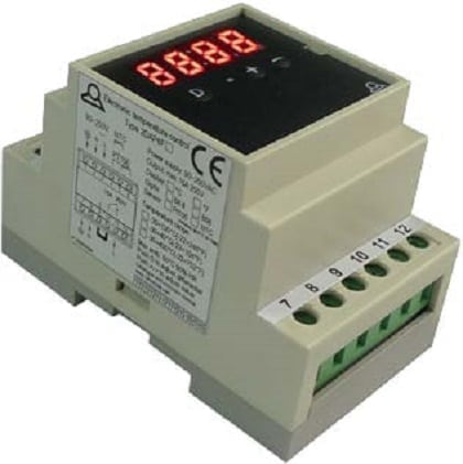
Electronic control thermostats
Electronic control thermostats
Electronic thermostat, multi range, control and manual reset action, for incorporation, NTC sensor
Bulb and capillary temperature limiters
Rod temperature limiter boxes
Immersion heater temperature control boxes
Pipe surface temperature limiter boxes
Remote temperature limiter boxes
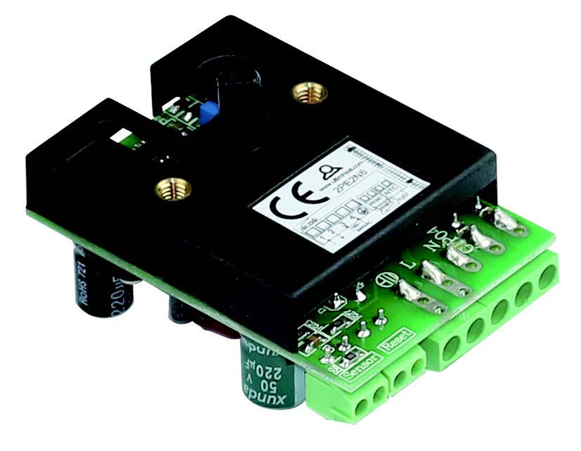
Manual reset electronic adjustable limiter, remote sensor, IP65
FIRE DETECTION
Technical informations associated to this product
-
Thermostats installation
The proper functioning of a thermostat depends primarily on the correct choice of the component, but also the conditions of its installation. Conditions used to calibrate regulating and control equipment in the factory are always ideal laboratory conditions, ensuring measurement accuracy and repeatability. These conditions are rarely those found in practice when installing thermostats. However, with a minimum of constraints, it is possible to optimize assemblies. -
Description of temperature controls
Used as control thermostats or as a safety thermostat with manual reset, these thermostats have a disc made of two different metals laminated together for temperature sensing element. These two metals have different expansion coefficients. -
Electrical contacts
As numerous mechanisms exist, we decided not to distinguish on the basis of constructive technique, but according to their operation speed, which is the key element. -
Electrical protection classes
The housings are designed to protect electrical equipment located inside. This protection must be considered in the electrical and environmental angles.)


