Reed switches contacts protection
1. The electrical contact system: reed switch or micro-switch
A certain force is required to actuate the electrical contact device. It can range from a few tenths of grams for systems with reed contacts with a power rating of 10 to 20VA
(0.5Amp), to 50 grams for snap action micro-switches with a 5Amp 250V rating
In general, the force required to operate an electrical contact increases with its electrical rating, and the power available on the detector depends on the paddle, piston or flap characteristics Most flow switches in this catalog use reed switches because they are used for detection level in low voltage and low current electronic circuits. This makes possible to design compact devices.
2. Reed switches
Reed switches are small glass bulbs with a flexible reed strip contact with a breaking capacity of 10 to 70VA, which has the particularity to close in the presence of a magnetic field. These glass bulbs are sealed and filled with argon or under vacuum, therefore they are protected from oxidation.
Reed switch applications in flow switches
| Suitable | Not suitable |
| Computer circuits | Small electrical motors , including small DC motors |
| Programmable logic controller (PLC’s) circuits | Power contactor coil circuits (Unless protected by an arc suppression circuit) |
| Small relays | Solenoid valves (Unless protected by an arc suppression circuit) |
| Solid state relay (SSR) trigger circuits | Incandescent lamps |
Reed switches contact protection
Switching no load or loads where the voltage is less than 5 Volts @ 10 mA or less, the contacts undergo little or no wear and life times in excess of billions of operations are expected. In the 10 Volt range, higher contact wear will take place. Switching 10 Volts @ 10 mA, life times of 50 million to 200 million operations can be expected.
When switching inductive loads such as relays, solenoids and transformers, reed switch contacts require protection in order to insure long, dependable life. When current is interrupted, the inductance or electrical inertia of the load generates a large high frequency voltage, which appears across the switch contacts. If the voltage is large enough, it can break down the medium in the gap between them, making a conductive path. This phenomenon is called arcing. Arcing can cause the contacts to burn, weld together or stick .The purpose of protection circuits is to prevent arcing, by shorting this voltage through an alternate path.
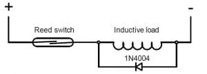
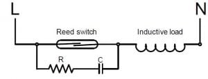
| DC load contact protection circuit with diode | AC load contact protection circuit with R/C circuit |
 |
 |
| A 1N4004 diode is connected cathode-to-positive .The diode does not conduct when the load is energized, but conducts and shorts out the peak transient generated voltage when the switch opens. A resistor can be added in series with the diode. | A resistor (R) and capacitor (C) are connected in parallel with the switch. The capacitor has high impedance at 50/ 60 hertz, and is essentially a short circuit to high frequencies of generated voltages. Capacitor value: C = I²/10 Resistor value (E= power supply voltage): R = E / (10.I (I+50 / E )) |
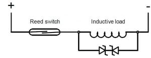
| DC load protection contact with Back to Back Zener diode | AC load protection contact with Varistor |
 |
 |
|
The peak transient voltage that occurs when the switch opens is decreased to a value equal to the back to back Zener diode voltage. The Zener diode should be sized for a voltage somewhat higher than the circuit source voltage. |
The varistor resistance decreases sharply when voltage reaches its trigger value, and shorts out the peak transient generated voltage when the switch opens. Varistor should be sized for a voltage somewhat higher than the circuit source voltage. |
Magnet displacement and reed switch operation in flow switches
| Piston types | Paddle and flap |
 |
 |
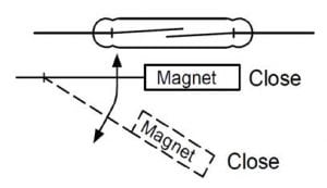
| When magnet located inside the piston arrives at the center of the reed switch, the contact closes. Therefore, piston movement is limited to achieve requested operation mode. | A magnet is located inside the paddle or inside the flap. When it arrives near the reed switch, the contact closes. |
